Did you find an error in this page? Please report it. eBook version 12.
In this chapter, you will complete step one of the schematic design workflow that you learned about in the previous chapter.
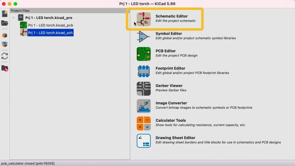
I will continue where I left off in the previous chapter. At this point, I have created a new KiCad project, and the main KiCad window is open. Click on the schematic editor button at the top of the right pane in Figure 3.5.6 (below).
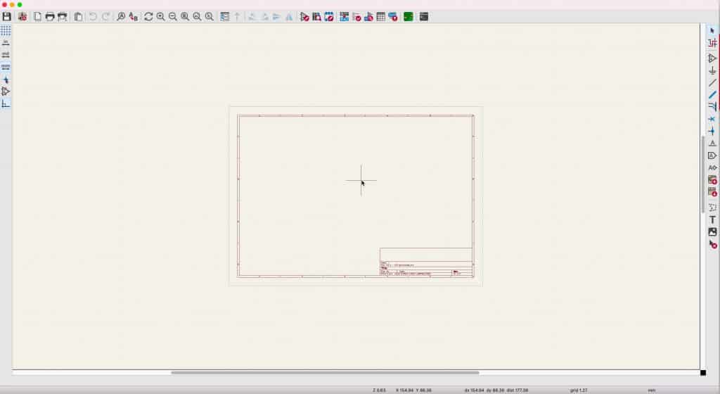
This will bring up the Eeschema window with a blank design editor (Figure 3.5.2):
It is worth taking a few minutes to look at some of the most important user interface tools and techniques you will use in all KiCad projects. Let’s start with the mouse.
I strongly recommend that you use a mouse with two buttons and a scroll wheel. I use a Logitech MX Master 2S (Figure 3.5.3):

Apart from the regular functions assigned to the left and right buttons, I use the scroll wheel to zoom in and out. In addition, the scroll wheel of this mouse is a middle button that allows me to pan. Because zooming and panning are so helpful in any CAD application, it is important to have a mouse that provides easy access to those functions.
To zoom, move the mouse pointer to the location in the editor that you want to zoom in, and then turn the scroll wheel. The zoom will always centre on the crosshair pointer.
To pan, press and hold the scroll wheel button and move the mouse to pan. It is also possible to zoom while you pan.
You can expose the context menu by pressing the right mouse button. Just click anywhere in the editor sheet, and click. The exact contents of the context menu will depend on what it is that you clicked on. A wire will give you a different context menu to a symbol, and so on (Figure 3.5.4).
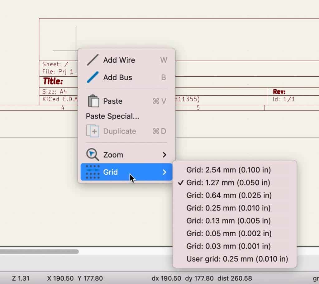
In the example above, I have right-clicked in an empty part of the editor sheet. Notice that the context menu contains submenus such as Zoom and Grid.
The editor sheet has a coordinate system that starts at the top left corner. The horizontal axis is the X, and the vertical is Y. There is a grid that supports drawing using a visual guide for the alignment of the various objects. There is also a snap-to-grid option to ensure perfect alignment. I use this option to ensure that wires and pins are aligned. At the bottom of the Eeschema window is the status bar. On its right side, you will find information about the current coordinates of the cursor, the distance between the cursor and the location where your reset the ruler, the grid size, and the measurement unit used (Figure 3.5.5).
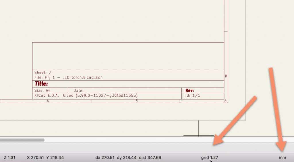
In the example above, my grid is set to 1.27 mm. You can change your grid and unit settings via the buttons of the left toolbar (Figure 3.5.6):
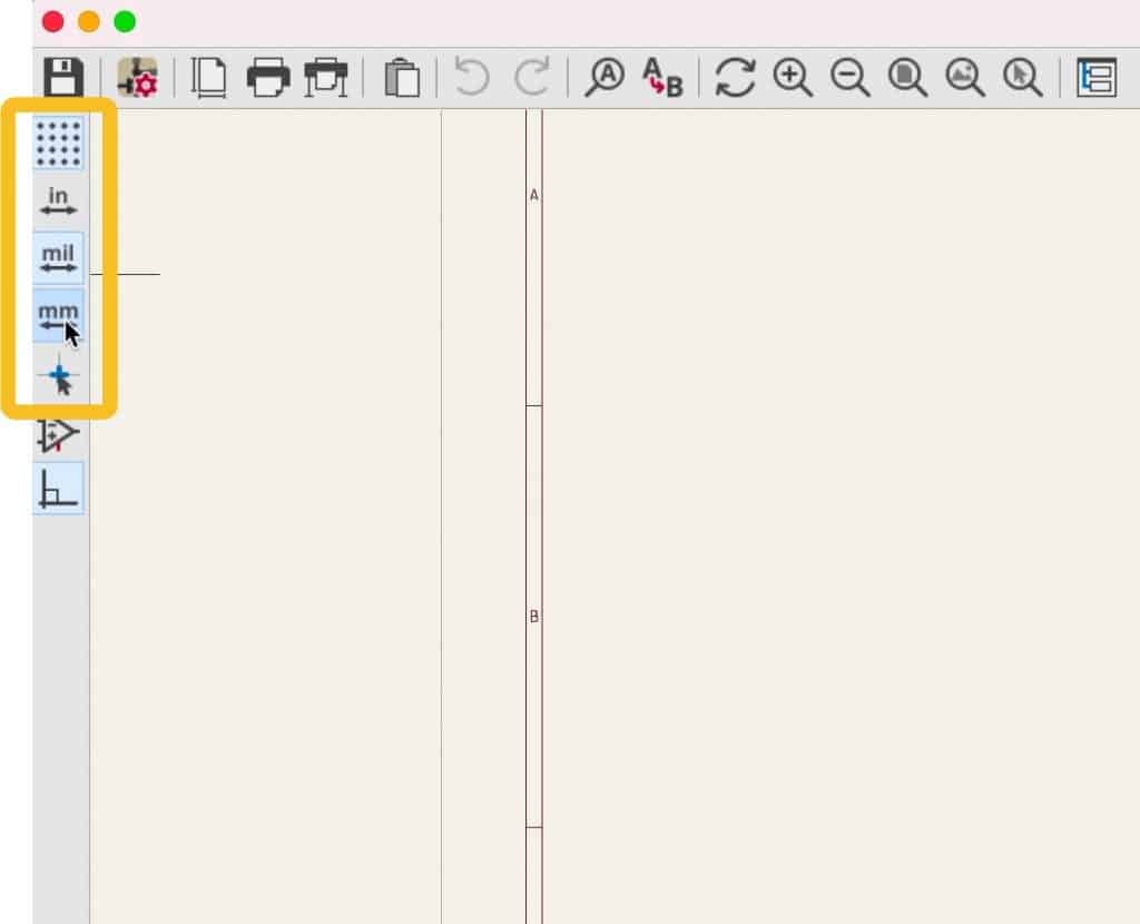
You can choose your preferred unit between millimeters, mils and inches, turn the grid lines on or off, and choose the type of cursor (regular or full crosshairs).
You can further control the appearance and operation of the grid via the Preferences window. Open the Preferences window, then click on Display Options under Schematic Editor (Figure 3.5.7):
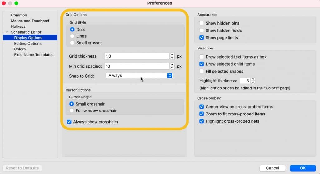
You can choose between three grid styles, two cursors, control the grid line thickness, minimum spacing, and enable the snap to grid feature (default is on, and I suggest you leave it at that).
Next, still in Preferences, click on Editing Options. You can see the various options there with my settings below (Figure 3.5.8):

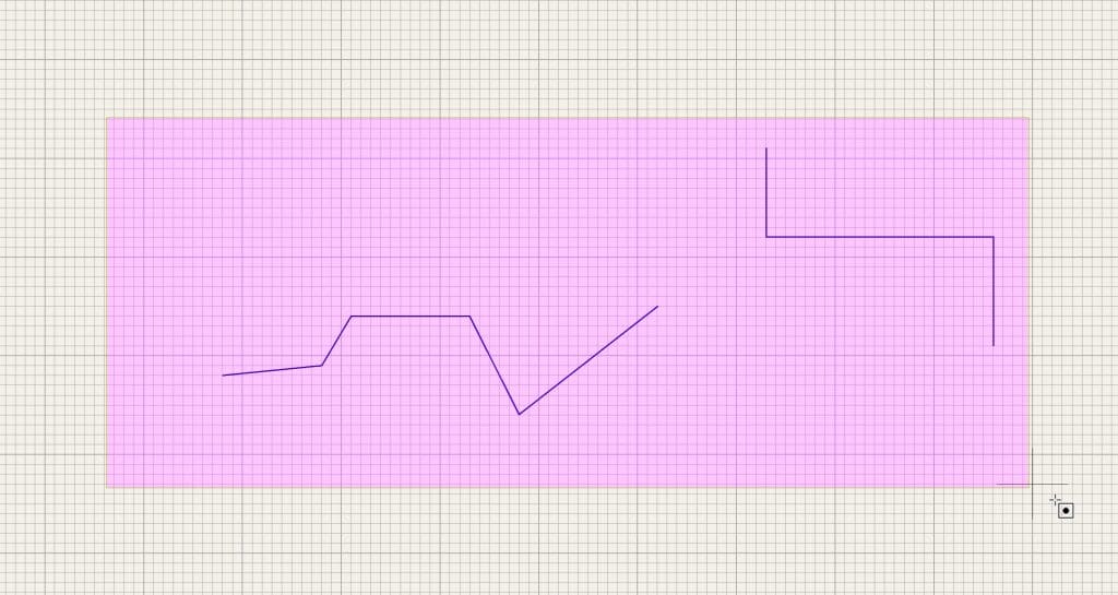
In the Editing group, the first option sets the orientation restrictions for wires. If checked, you will only be able to draw horizontal and vertical wire segments. I believe that with this setting, you will be able to produce more visually pleasing schematics, so I suggest you leave it checked. You can see an example below; the wires in the left contain horizontal and vertical segments only, and the one in the right has wire segments in non-90 degree angles (Figure 3.5.9).

Take a few moments to explore the options in the Schematic Editor tabs in the Preferences window before you continue (especially the ones in Display Options and Editing Options). You can learn more about these options in a dedicated chapter later in this book.
Remember that you can use the ESC key (type ESC twice) to exit any activated tool. To delete multiple items in a schematic, use your mouse to enclose those items in a box and highlight them, and then hit the Delete key (Figure 3.5.10):
To configure the grid size and the quick-select settings, you use the Grid Settings window, accessible from the View menu (Figure 3.5.11).
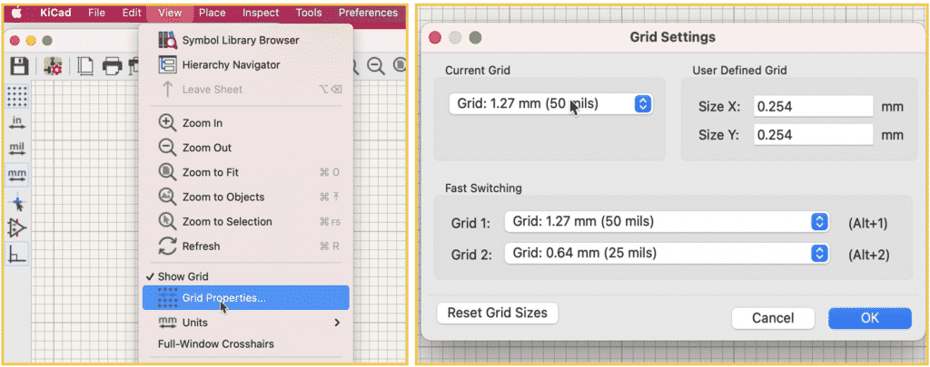
Generally, in busy schematics, you will want to use a small grid size. You can also set grid size keyboard shortcuts (Alt-1 and Alt-2) to specific grid sizes. You can see my settings in the figure above.
The last item in my to-do list in this first step of the schematic design workflow is to fill in the project information in the Page Settings window. Access the Page Settings window from the File menu (Figure 3.5.12):

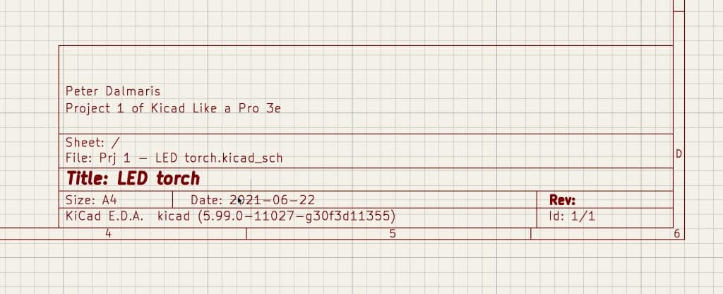
The fields in the Pages Settings window can contain any text that you type in and will appear in the schematic sheet label (bottom right corner). You can provide any information you think is helpful to the reader of the schematic.
Once completed, click OK, and notice how the information you entered appears in the schematic sheet (Figure 3.5.13):
Step one of the schematic design workflow is now complete. Let’s continue with step two in the next chapter.