Did you find an error in this page? Please report it. eBook version 12.
In this chapter, you will complete step five of the schematic design workflow, that you learned about in the second chapter of this part of the book. This chapter will show you how to give custom names to the nets you created in the last chapter.
But first, what is a net? Think of a net as a representation of an electrical connection between two pins. In the circuit in Figure 3.9.3 you can see four wires, that connect four pairs of pins. For each of those wires there is a net. KiCad uses nets to keep track of which pins are connected to which other pins. While we (i.e. the “designers”) see wires, KiCad “sees” nets.
If you have two wires that intersect and are electrically connected, both wires will belong to the same name. Therefore it is possible to have nets that contain more than one wire. You will see this frequently in later projects in this book. In this first project, it happens that each wire corresponds to one net.
It is possible to give nets custom names so that it is easy to identify. While you don’t have to name all nets, it is good practice to give custom names to some important nets, such as those for the ground and operating voltage levels and signal nets.
To give a custom name to a net, you will use the net label tool. You can enable this tool from the right toolbar (Figure 3.9.1).
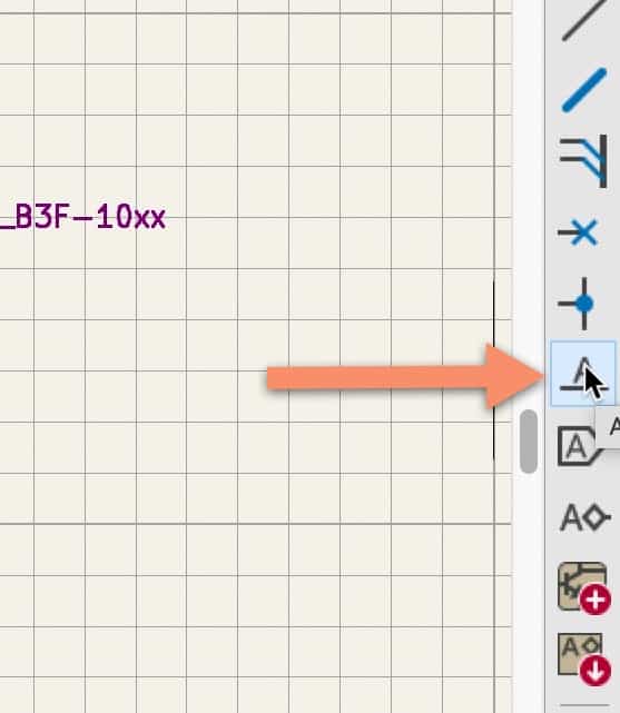
To use it, click on the button to enable it (or type the “L” hotkey), and then click anywhere in the editor to bring up the label properties window. In the label text field, type the name of the net. In my example, I have typed “LED_cathode” (Figure 3.9.2, left). Click OK to create the label.
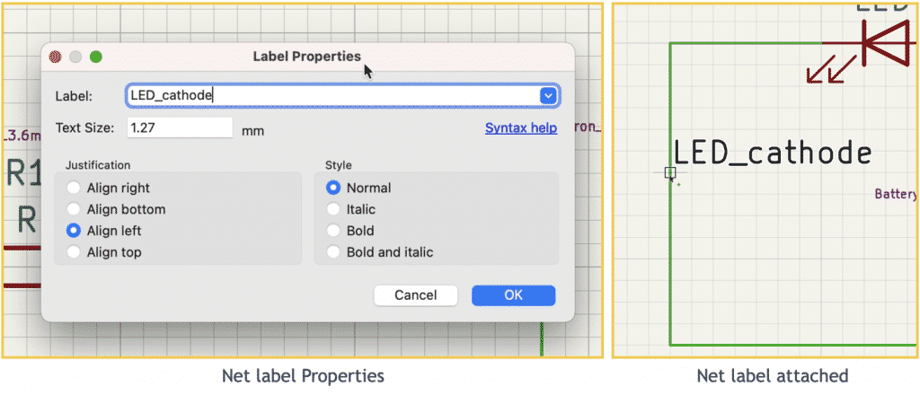
The new label will be attached to the mouse cursor when you dismiss the net label properties window. Move the small box of the label to overlap any part of the wire you want to name, and click to commit it.
That’s it. The wire and its net have a custom name.
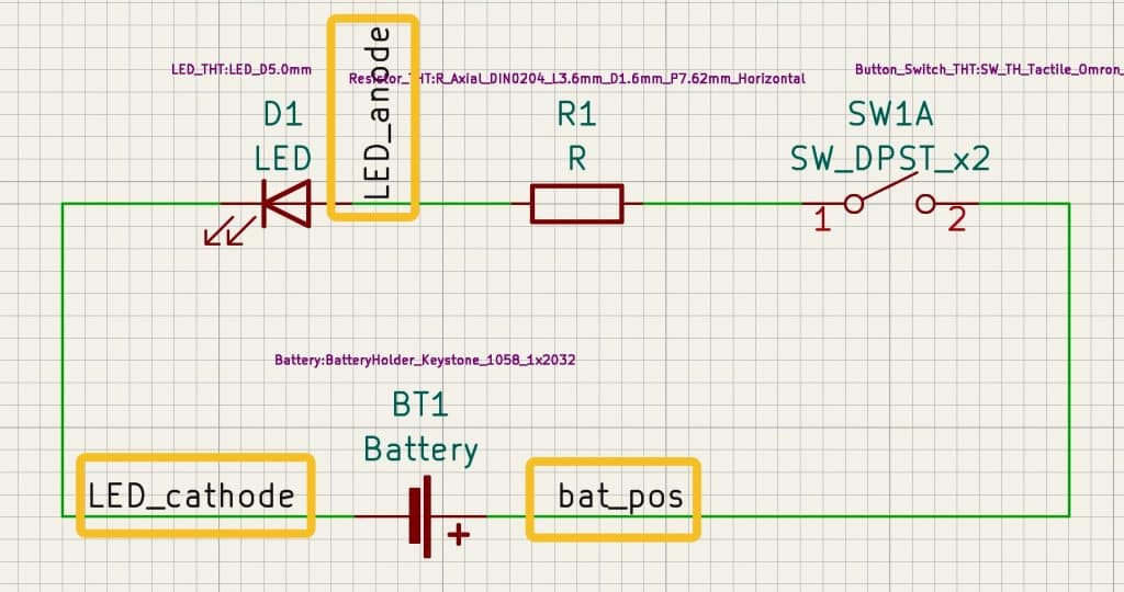
Continue using the same process to create two additional named nets. Below is a list of all nets in this schematic:
- LED_cathode.
- LED_anode.
- bat_pos.
I did not give a custom net name to the wire that connects the resistor to the switch.
Below is the schematic at the end of step five (Figure 3.9.3):
In the next chapter, I will show you how to perform an electrical rules check.